

Abstract
This case study focuses on the analysis and repair of a riser pipe in a waste heat boiler system. The initial damage resulted from inadequate tapering at the welded joint, causing high stress concentration and fatigue cracks. The first repair involved cutting and replacing the damaged section, performing proper taper transitions, and applying preheating and post-weld heat treatment. However, thermal stress during the repair process led to a bulge near the repaired joint. To prevent recurring failures, two repair solutions were proposed. Solution 2, which involved simultaneous preheating for all pipes, was successfully implemented. This case study highlights the importance of proper tapering practices and considering thermal expansion in equipment repairs.
Introduction
The waste heat boiler is a system used to recover the heat from the process stream after passing through the reaction equipment. This recovered heat is utilized to generate steam through equipment E04208 (Waste Heat Boiler No. 1), E04501 (Loop Waste Heat Boiler), and E04210 (Waste Heat Boiler No. 2). The generated steam is then sent to S04201 (Steam Drum) via riser pipes.
The damage in question is located on the riser pipe connecting equipment E04208 and S04201 (Figure 1, Figure 2). Operation condition of riser pipe is as table 1.
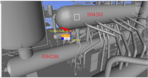
Figure 1. Location of damage
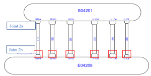
Figure 2. Location of joint 2a
Parameters | Temperature, oC | Pressure, Mpa |
Design | 336 | 13.1 |
Operation | 324 | 11.8 |
Material of riser pipe | 15NiCuMoNb-5-6-4 | |
Table 1. Operation condition of riser pipe
History of damage
First damage:
After 9 years of operation, a crack was discovered at the weld joint 2a (Figure 2, Figure 3). To determine the cause of the damage, the crack sample was collected (figure 4) and perform failure analysis. The results are as follows:
- The crack originated from the inside and propagated outward.
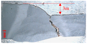
- The crack started at a position with high stress concentration due to the misalignment of thickness at the welded joint without a proper taper transition. The misalignment at the weld joint was 3mm (Figure 5).
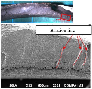
- The fracture shows fatigue mode with the propagation from the weld zone at the inner surface in the circumferential direction (Figure 6).
- The material composition, hardness, and strength were consistent with design standards.
Figure 3. Crack at toe of weld joint 2a |
Figure 4. Crack sample |
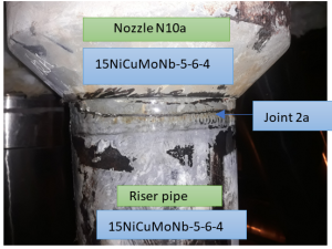
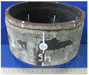
Figure 5. Misalignment of 3 mm at the weld |
Figure 6. Sign of fatigue propagation |
Repair method for weld joint 2a (first damage):
- Cut the riser pipe at weld joints 2a and 2b (Figure 2) and replace it with a new pipe.
- Perform a proper taper transition to avoid stress concentration at the welded joints with difference thickness.
- Carry out welding for both joints 2a and 2b.
- Apply preheat at 200°C and PWHT at 620°C for both weld joints as per welding procedure.
Second damage
After completing the first repair, a bulge was observed near weld joint 2b of the riser pipe. The diameter of the bulged area measured 172mm, compared to 168mm at the unaffected area (figure 7).
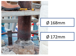
Figure 7. Bulged riser pipe after first repair
Causes of pipe bulging:
Base on the configuration of this system (figure 1 and 2), all the pipe no. 1 to 6 will expand and contract simultaneously during operation. However, during the repair of riser pipe no. 1, only pipe no. 1 experienced heating due to preheating and PWHT, while pipes no. 2 to 6 remained fixed. This led to excessive thermal stress on pipe no. 1, causing it to bulge.
Possible repair solutions
Based on the analysis above, it is evident that the initial damage occurred due to inadequate tapering, resulting in high stress concentration. This stress concentration eventually led to the formation of fatigue cracks over an extended period of operation. The second damage arose from an inappropriate repair process for the initial damage. Consequently, in order to prevent recurring failures, it is necessary to develop an appropriate repair procedure that accommodates thermal expansion at both ends of the pipe section and reduces the stress concentration.
To reduce stress concentration, all joints between pipes with different thicknesses shall be properly tapered.
To accommodate thermal expansion during the repair process for the riser pipe, several solutions can be implemented, such as:
Solution 1: Preheat and PWHT all the pipe 1 to 6 simultaneously.
This solution can be done by the following step (figure 8):
- Step 1: Weld, preheat and PWHT for joint 2a.
- Step 2: Weld, preheat and PWHT for joint 2b and all other riser pipe no. 2 to 6 at same heating and cooling rate.
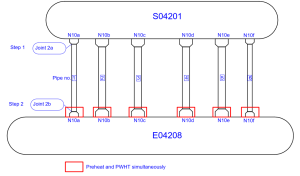
Figure 8. General step in solution 1
This solution has some disadvantages as below:
- PWHT may cause negative effect on mechanical properties of pipe no. 2 to 6.
- Simultaneous heating until PWHT temperature (6100C) is not easy. The higher temperature is the higher risk of damage PWHT machine. One PWHT machine is damage, the job need to restart.
Solution 2: Preheat all the pipe 1 to 6 simultaneously
Similar to solution 1, preheat and PWHT shall be done for joint 2a. but for joint 2b, only preheat is required, no PWHT is required. In order to do this, new welding procedures shall be developed by appling the buttering layer on the final weld (joint 2b). Buttering material is required to satisfy the following condition:
- Suitable for process operation condition (temperature, fluid).
- No PWHT is required when welding buttering material to buttering material.
In this case, we use ER70S-A1 as buttering material and carry out preheat simultaneously for joint 2b and pipe no. 2 to 6 (figure 9).
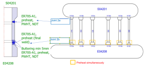
Figure 9. General step in solution 2
This solution has following advantage:
- No PWHT, no negative effect on mechanical properties of pipe no. 2 to 6.
- Simultaneous heating until preheat temperature (1500C) instead of PWHT temperature (6100C).
Selected repair solution
The selected repair solution was Solution 2, as it provided the advantage of avoiding PWHT and its potential negative effects on the mechanical properties of pipes 2 to 6. The repair steps as figure 10 were carried out successfully without any observed bulging.
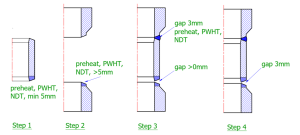
Figure 10. Repair step
Conclusions
This case study highlights the importance of adhering to proper tapering practices when repairing equipment in refineries and petrochemical plants. In the initial damage scenario, inadequate tapering at the welded joint resulted in high stress concentration, leading to fatigue cracks over time. The second instance of damage occurred due to an inappropriate repair process that did not account for thermal expansion.
By implementing an appropriate repair procedure that included proper tapering, the risk of stress concentration and subsequent damage was effectively mitigated. The selected repair solution, which involved simultaneous preheating for all pipes and no post-weld heat treatment for joint 2b, proved successful in avoiding further failures and bulging.

