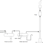
Introduction
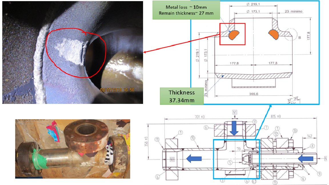
- Local metal loss was found on the TEE after 10 years of The metal loss is due to erosion/erosion-corrosion of carbamate solution. Thickness measurement at the metal loss and surrounding area have been done.
- To demonstrate the structure integrity of the TEE that contains the local metal loss, Fitness for service have been done.
- Below is the operating/design condition and construction material of the TEE.
| Design | Operation |
Temperature (0C) | 234 | 180 |
Pressure (MPa) | 16.2 | 14.5 |
Medium | Carbamate solution | |
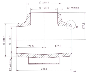
Material | A182 F316L UG | |
Fitness for service (FFS)
FFS based on part 5, API 579-1/ASME FFS-1 have been carried out as follow.
FFS level 1, level 2
- Level 1 Assessments are limited to Type A Components. The only load considered is internal pressure, and a single thickness with one or two surface area dimensions are used to characterize the local metal loss.
- Level 2 Assessment rules provide a better estimate of the structural integrity of a Type A or Type B, Class 1 component subject to internal pressure when significant variations in the thickness profile occur within the region of metal loss.
- Since assessment component belongs to type B, class 2, FFS level 3 shall be used.
FFS level 3
Protection Against Plastic Collapse
Three alternative analysis methods are provided in VIII-2, Part 5 for evaluating protection against plastic collapse. A brief description of the analysis methods is provided below.
- Elastic Stress Analysis Method
- Limit-Load Method
- Elastic-Plastic Stress Analysis Method
In this assessment, Limit-Load Method is applied.
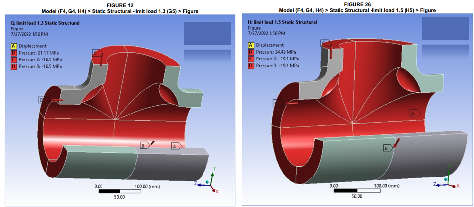
Limit-Load Analysis Method
The assessment procedures for the Limit-Load Analysis Method shall be in accordance with VIII-2, Part 5, paragraph 5.2.3 except that the load case combinations that incorporate the Allowable Remaining Strength Factor (RSFa) as shown in Table 2D.3 may be used in the assessment. The recommended value for RSFa is 0.9. In this assessment, RSFa is 1. It is more safety.
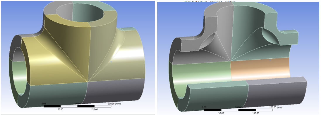
Step 1. Develop a numerical model of the component including all relevant geometry characteristics. The model used for the analysis shall be selected to accurately represent the component geometry, boundary conditions, and applied loads. The model need not be accurate for small details, such as small holes, fillets, corner radii, and other stress raisers, but should otherwise correspond to commonly accepted practice.
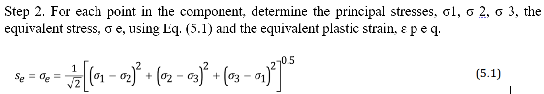
Step 2. Define all relevant loads and applicable load cases. The loads to be considered in the analysis shall include, but not be limited to, those given in Table 5.1.
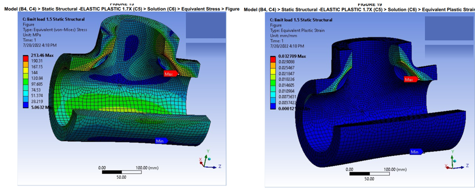
Step 3. An elastic perfectly plastic material model with small displacement theory shall be used in the analysis. The von Mises yield function and associated flow rule should be utilized. The yield strength defining the plastic limit shall equal 1.5S.
Step 4. Determine the load case combinations to be used in the analysis using the information from Step 2 in conjunction with Table 5.4. Each of the indicated load cases shall be evaluated. The effects of one or more loads not acting shall be investigated. Additional load cases for special conditions not included in Table 5.4 shall be considered, as applicable.
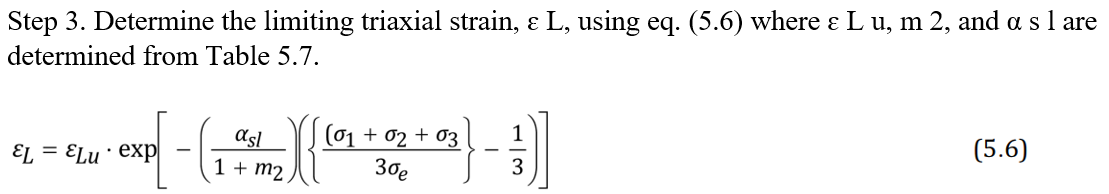
Step 5. Perform a limit-load analysis for each of the load case combinations defined in Step 4. If convergence is achieved, the component is stable under the applied loads for this load case. Otherwise, the component configuration (i.e., thickness) shall be modified or applied loads reduced and the analysis repeated. Note that if the applied loading results in a compressive stress field within the component, buckling may occur, and the effects of imperfections, especially for shell structures, should be considered in the analysis (see 5.4).
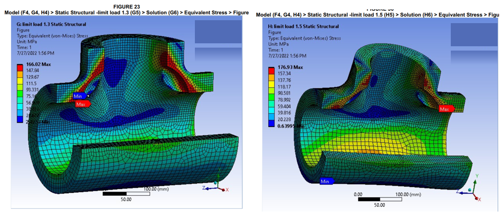
Since convergence is achieved, equipment passes FFS level 3 – protection again plastic collapse.
Protection Against Local Failure
Two analysis methodologies are provided for evaluating protection against local failure to limit the potential for fracture under applied design loads.
- Elastic Analysis Method.
- Elastic-Plastic Analysis Method.
In this assessment, Elastic-Plastic Analysis Method is applied.
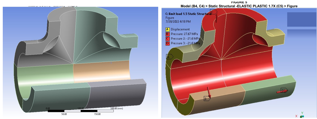
Elastic-Plastic Analysis Method
The assessment procedures for the Elastic-Plastic Analysis Method shall be in accordance with VIII-2, Part 5, paragraph 5.3.3 except that the RSFa may be applied for load case combinations as shown in Table 2D.4. The recommended value for RSFa is 0.9. In this assessment, RSFa is 1. It is more safety.
Step 1. Perform an elastic–plastic stress analysis based on the load case combinations for the local criteria given in Table 5.5. The effects of non-linear geometry shall be considered in the analysis.
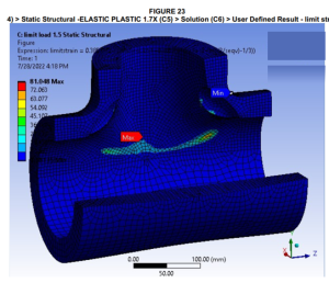
Step 4. Determine the forming strain ɛ c f based on the material and fabrication method in accordance with Part 6. If heat treatment is performed in accordance with Part 6, the forming strain may be assumed to be zero.
Step 5. Determine if the strain limit is satisfied. The component is acceptable for the specified load case if eq. (5.7) is satisfied for each point.
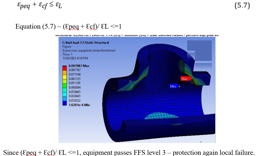
Conclusion:
TEE passes FFS level 3 assessment, the component can be returned to service.